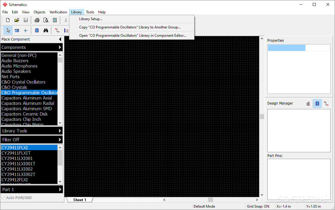


#Diptrace pattern to pad trial
And when I ran a trial of make a PCB from my schematic, it had no errors and actual looked like a PCB. I'm good with assigning a pattern to a component. I think I understand the PAD and the silk (outline). I do not have a handle on the layers and process of making a board.

I am bumping that way up to 0.100" per bend. This makes getting in and out with an iron a snap if you need to do any rework or repairs." The lead bend from body at. While you can get them closer, if you've got the board space use it. As far as component to component spacing, I tend to lay out 1/2w and 1w resistors with about 200 thou ( 0.51mm) spacing between them, and 1/4w at around 150 thou (0.38mm). With respect to the pad and hole size, take the nominal lead diameter and add 12thou (0.3mm) and round up to the nearest drill size for your hole, then double that value for the pad size. Open the editor and using the same component properties menu as with pattern pads choose '2 sides' in type menu, in width and pin spacing type the numbers of your choice, 'left pins' and 'right pins' type one and one. This should be approximately IPC standard but I may be wrong so don't quote me on that. Lets start with the pattern - launch diptrace, you see the starting menu - choose pattern editor. Ideally you want about 100thou (0.25mm)between the bend and the body. "The thumb rule I like to use is 1w resistors get 700thou (1.78mm) pad to pad spacing, 1/2w 600 (1.52mm), 1/4w 500 (1.27mm), etc. Is that more acceptable? Here are AMDOC's suggestions.
#Diptrace pattern to pad iso
Do I use ANSI or ISO drill bit sizes? I tend to like my units to be mm, but all the drill sizes are in 1000ths, and that's what the doctor ordered. Which should I pick and why isn't round an option? (I think I'v picked oval) I've followed AMPDOCTOR's rules of thumb for PAD size and spacing. In the Pattern editor my options for PAD shape are Ellipse and Oval. We can see that for the first pattern all pads are connected to vias, for the second one two rows are without vias (i.e. That's because I keep screwing up my calc's and I am accumulating components. thermal pad is smaller than 4.0×4.0 mm, stencil pattern is 40 smaller than the pad area It is also advisable to create the stencil design as segmented squares or rectangles instead of just 1 whole paste area for thermal pads, this applies to pads with land area over 4.0 mm. I have 30-50 set up, but I'll only need a dozen. Hi, I've been setting up my component and pattern libraries in DipTrace.


 0 kommentar(er)
